• Welcome to the Yamaha FZ6 Forums. Member registration disables ads and allows you to post and share. Register Here.

Clicking solanoid

I'm experiencing this topic right now on my cafe racer. Got the dreaded clicking the day after washing the bike (clue #1). I checked the static voltage (13.6VDC...LiFePH4 battery) and the voltage at crank (or click in this case) which was above 13VDC...which told me that the starter wasn't receiving current. Jumping the starter solenoid I got a normal start - so that rules out the starter itself.

I ordered a new starter solenoid from Amazon and...same result. This tells me that the problem is likely in the wire harness somewhere. So this weekend I will check all of the connectors in the starting chain for corrosion. I'm sure that I had a borderline connection somewhere and washing the bike gave it just enough moisture to create some corrosion. This bike has lived in a dry garage for at least 20 years and the only time it gets wet is during a wash. Time to switch to a dry wash system :)View attachment 93439
Gary,
Do you have a a schematic I could look at for that beauty? Like maybe a PDF @Gary in NJ
 
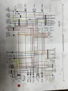
My wire harness is modified. I’ve eliminated the decompression solenoid as well as the clutch and kick stand interlocks. With that said, here is the schematic that I use.
 

Attachments

  • IMG_4506.webp
    IMG_4506.webp
    419.2 KB · Views: 6
I added a manual decomp lever on the left side control, but I’ve yet to use it. The bike cranks fine without. I guess there is a potential for the piston to stop at the exact wrong spot…but I have a feeling it’s a 1:1,000,000 chance.
 
My wire harness is modified. I’ve eliminated the decompression solenoid as well as the clutch and kick stand interlocks. With that said, here is the schematic that I use.
Thank you for the schematic. Interesting how they've changed the safety protocol. They achieve the same functions.
 
I'm going way off topic here...but what the hell. The issue with my cafe racer has gone from bad to worse...and the problem doesn't have anything to do with the solenoid.

I couldn't get to the bike for a few weeks and today was the day I put aside to troubleshoot the solenoid issue. The first thing I did was to try another start to to make sure that the problem didn't "self correct", but when I turned the key to the "ON" position nothing happened. I checked the battery voltage and all is good. From there I did the following:

- Checked the continuity at the ignition switch. All good
- Checked the Fuses. Both are good

Here is where things start to go down the electronics rabbit hole. With the switch in the ON position:

I get good voltage through the Red and Red/Black at the fuse, but no voltage at the Red and Red/White in the other fuse. I do get continuity AND voltage between the Red/Black and both Reds, but nothing with the Red/White.

At the Regulator/Rectifier I get no voltage on any wires, but I get continuity between all three (red/white, orange/black and black/white). I'm "thinking" that I should be able to see battery voltage on the orange/black and no continuity on that wire, so I suspect a short in the harness.

Also, the lack of voltage at the red/white at the fuse is a head scratcher.

I think I have a short in the harness.
 
Interesting. There should be a home run right from the positive battery terminal to those two 20 amp fuses. Are you saying the is no battery voltage at the fuse that supplies the red/white wire?
 
No voltage on the red/white wire at the fuse. But that makes sense since red is the feed to the red/white wire. I have unswitched battery voltage from both reds to ground. My decomp controller is still in the system (I thought I deleted it but it’s part of the start circuit - it’s been 10 years since I built the bike) and I’m starting to think it has failed. That would explain the clicking solenoid…but I’m not sure if it contributes to the lack of system power. The first stop from the fuse for the red/white wire is the decomp controller.
 
I'm living in opposite land. Check out the results of some voltage and continuity tests in the attached pdf. Most shocking is the last line: Voltage @ Battery (+) to Harness (-): 13.4vdc with the switch off and 0vdc in the on position. And I've checked the continuity of the switch a dozen times....even rebuilt it once.
 

Attachments

You should see +12 vdc at the red/white wire from that 20 amp fuse. If not there is a loss of +12 vdc red wire from the battery or that fuse is open. I've also seen fuse holders fail.
You might try disconnecting the 2 yellow with tracer wires from the decomp assembly and connect those wires to bypass the decomp assembly. This should allow the starter relay/solenoid to activate. The +12 vdc travels through the side stand relay to the engine stop switch to the starter button through the clutch switch. Of course some of that wiring goes through harness at the bars and might be worth ringing out.
 
I think a bad ground at harness (-) could give you that last line result?
Under that condition, measure harness (-) to chassis.
You Sir, go to the head of the class. I just went outside and ran a jumper cable between the (-) post on the battery to the chassis ground. Not only did the lights come on, but the bike cranked right over.

I checked the ground connections many times, and I'm 99.9% sure that I would not have thought of fried ground cable without your post. The ground cable has good continuity...but I guess there are enough broken or corroded strands within the casing that it can't carry enough current.
 
Last edited:
Glad to hear it was a relatively simple fix!
You will always find full supply voltage at all points on the 'hot' side of an open circuit. So I expected you would have measured 12V from harness (-) to chassis when the ignition switch was on. Had it been a short somewhere I would expect a blown fuse.
As you suspected, probably enough continuity to measure ok for resistance when no current was required.
 
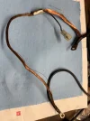
To illustrate how insidious electrical gremlins can be, I cut the casing off the cable. Just below the crimp where the cable goes from 6 to 8 gauge you’ll see that the copper is all black. I’m surprised that this corrosion caused such a failure (I expected to see green) but I guess that it wouldn't be long until this copper turned green. Clearly a failed cable. This cable didn't show any signs of failure through the multi-meter, but it could't handle starting current...and then it couldn't even handle the current for basic functions.

I ordered another from eBay because it was only $10 shipped (can’t make one that cheap) but if I do decide to make my own I’ll just make it 8 gauge the entire length and I’ll move the harness connection to one of the ends to avoid making a mid-length crimp.IMG_4514.webp
 
Back
Top