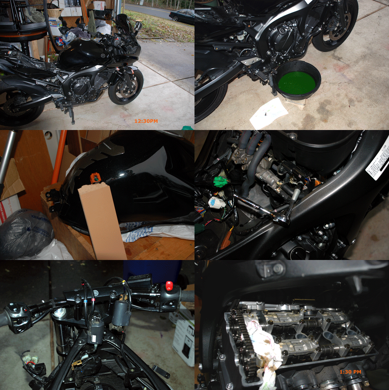
I've never seen a "How to" on TB R/R so you'll be the first.
I've had the TB off another guys bike and its pretty straight forward. Two tools you must have to make it simple - acquire both 3 and 4mm allen wrenches that are at least 6" long. If these can't be found, grab the longest shank of this size and 1/4" drive with a long extension. OR make your own by cutting an Allen wrench and fitting it to a 3 or 4 mm socket.
By the Book you also need a volt meter, but you can use the Diag mode to set it.
Pull the seat, tank, battery and air box. Follow one of the "How to Check Valve Clearance" threads, same process. With the proper tools you have access in about 15". In my album on this site are many pictures. You might look through them... -->
Final Impact, Bike P O R N Because the Idle Air Control Valve is connected to the cooling system, you might just go ahead and drain it. It should be done every couple years anyway. Mix 50/50 with distilled water and Glycol. Refill is something less than 2 quarts total.
In this case, I popped the fairing free too (valve clearance check). Overkill for your cause.
Pay attention to how the fuel line decouples... ^^
Set tank aside with Fuel line up as shown. Some may leak from gravity.
In this pic you see the hack 4mm tool to free the air box. With the battery out, bolts removed, loosen the 4 hose clamps, loosen the 4 Throttle Body clamps at the top, and remove air box.
Now you gain access and it looks like this:
Remove the jamb nuts holding the throttle cables in place. Best done from the cable SHEATH side. RETURN THEM EXACTLY TO THAT DISTANCE, otherwise you get them out of adjustment and throttle sticks. Once the cable body is free, twist the throttle shaft to align the cable end and free the cable end. Try not to kink the cable.
View from above. You could just pull the Rubber hoses from the IACV and plug them, but I'd suggest draining the coolant if its close to due. Unplug any connectors to the TB and take pictures along the way for cable routings....
Loosen 4X 3mm clamps at the BASE of the TB's. Now there is next to nothing holding the TBs in place. Rock them until they come free and pull straight up.
Here is the TPS. Do ALL of your adjusting while the throttle bodies are free of the engine bay. As you can see, access is limited by the frame. So, attach battery and cables, go into DIAG and set the TPS for values listed in FSM. You're goal should be to center the highest and lowest numbers seen. I.e. you don't want 25 & 130, shoot for 16 and 98 or so. You just need to rotate the TB with the NEW TPS attached. You do not need the Fuel tank or injectors plugged in. Just the TPS and battery. Make your adjustments BEFORE setting the TB assmebly onto the engine. Verify by rotating the Throttle Shaft and Watching in DIAG mode.
If all goes well you end up with this assembly out on the work bench!
Use a VOLT METER AND SET the TPS OUTPUT / Key ON:
Throttle position sensor setup:
Output voltage (at idle) 0.63-0.73 V
• Positive tester probe at Yellow wire
• Negative tester probe at Black/Blue
Resistance 4.0–6.0 kΩ
In Diag Mode; Verify Range is within specification:
• Fully closed position 15–17
• Fully opened position 97–100
Note: The Idle value is MORE important than the WOT value.
PS - DO NOT drop ANYTHING into the OPEN intake runners! MAJOR ENGINE DAMAGE WILL RESULT:
- Confirm bolts are secure on TPS.
- Clean the boots at the base and TB outlet.
- Begin installation of TB's onto intake.
- That's all I've got for now. Take your time putting it back and DOUBLE Check everything!!
TAG: JJD952 Throttle Body Replacement
From post 3 of:
How to Change my Throttle Position Sensor (TPS)