• Welcome to the Yamaha FZ6 Forums. Member registration disables ads and allows you to post and share. Register Here.

Wiring motogadget mo.lock

BucksRider

New Member
Joined
Sep 19, 2017
Messages
29
Reaction score
0
Points
1
Location
Bensalem, PA
Visit site
Hello all,

I am trying to wire in a motogadget mo.lock nfc ignition using their optional wiring harness. I have linked the products for reference. Note: I am not using the mo.unit.

My existing ignition looks like this:
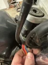
FZ6MainSwitchWiring.webp

The orange wire connects to the red wire behind the wire cover before the wires get to the connector:
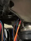
OrangeWire.webp

Here are the connectors:

FZ6MainSwitchConnectors.webp

The red wire (and orange wire) is constant +12V from the battery, and when switched, the brown wire (which becomes brown/blue after the connector) gets 12V. This then goes to the signal, headlight, ignition and tail light fuses. (white connector in picture)

The two remaining wires (red connector) are blue/yellow (which becomes blue/white after the connector) which goes to the ECU, and blue/black which goes to the starting circuit cut-off relay and the clutch switch. When the main switch is off, these two wires get 0V, when on they get 0.7V.

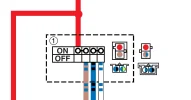
For reference, this is the connector pinout from the wiring diagram:
1732572098998.webp


When switched on, there is continuity between the red and brown wires, and between the blue/white and blue/black wires.


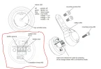
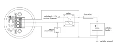
Here are the instructions from motogadget website:
1732573000119.webp

  • Cable from relay via fuse to +12V and ground: 60 cm /23.62"
    Cable from relay to mo.lock NFC: 150 cm /4.92'
    Cable from relay to on-board power supply: 150 cm /4.92'
  • Integrated relay socket
  • Integrated 40A vehicle main fuse
  • Pre-assembled battery connection (M6 ring eyelets)

Can anybody help me figure out if it is possible to use this device and if so, how the heck to wire it? The blue/white and blue/black wires are really throwing me off.

Thank you in advance for your help and guidance.
 
Looking at the photo there are brown, red and black wires that come out of the harness (in addition to the +12vdc and ground) that complete the installation. Where do the instructions say that these should be connected?
 
Looking at the photo there are brown, red and black wires that come out of the harness (in addition to the +12vdc and ground) that complete the installation. Where do the instructions say that these should be connected?
These 3 wires go to the ignition switch unit:

1732583711129.webp

Red to battery plus terminal, black to battery ground terminal, and brown to ignition plus terminal.
 
So when the OEM switch is in the ON position I believe that the brown/blue, blue/white and blue/black wires receive 12VDC. The 30 terminal from the relay goes to 12VDC Switched Onboard Power. So it would appear that the brown/blue, blue/white and blue/black wires get connected to terminal 30 on the relay.
 
So when the OEM switch is in the ON position I believe that the brown/blue, blue/white and blue/black wires receive 12VDC. The 30 terminal from the relay goes to 12VDC Switched Onboard Power. So it would appear that the brown/blue, blue/white and blue/black wires get connected to terminal 30 on the relay.
The brown/blue wire does get 12VDC when the OEM switch is in the ON position, but the blue/white and blue/black do not. They measure 0.7 VDC when OEM switch is on the ON position.
 
Are you measuring the voltage after the ECU? There is a DC to DC converter within the ECU that takes the 12V and reduces it to the sensor reference voltage. There is no means for voltage conversion before the ECU. Its line voltage. The switch diagram you provided shows the direct connection.

 
Are you measuring the voltage after the ECU? There is a DC to DC converter within the ECU that takes the 12V and reduces it to the sensor reference voltage. There is no means for voltage conversion before the ECU. Its line voltage. The switch diagram you provided shows the direct connection.

[/URL]
That's what's throwing me off - I am measuring at the red connector (which is between the main switch and the ECU). I have no idea where it is getting the low voltage from.

Just to clarify - there is no continuity between the (red and brown/blue) pair of wires, and the (blue/black and blue/white pair) of wires when the main switch is in the ON position.
 
I read through that thread (painful) and they suggest a second relay for the 0.7V line. It would appear that power is routed from the 12v switch (blue/black) into the ECU and then back to the switch via the white/blue (0.7v) for switching purposes.
 
I read through that thread (painful) and they suggest a second relay for the 0.7V line. It would appear that power is routed from the 12v switch (blue/black) into the ECU and then back to the switch via the white/blue (0.7v) for switching purposes.
Yea that’s what I was thinking.. I’m going to test that by unplugging the red plug and measuring the voltage.. when unplugged, if that theory is correct, one of the wires should see 0.7V and the other should be 0V. If that is the case I will get a second relay and try it that way.
 
Important note: The 2 lighter gauge (blue with black) and (white with blue) wires are connected together when the key is in the on position. Do not connect to 12vdc + or ground these wires.
We were on a group ride up on Palomar mountain where a rider broke his key off in the seat lock tumbler, Now he couldn't get gas or start the bike. I opened the harness and connected the heavy red to the heavy brown with blue. Then I connected the light gauge (blue with black) and (white with blue) wires. and we went straight back to San Diego. He got a locksmith to get the remaining broke key out of the tumble and made a new key. He gassed up and came back to my place where I offered to repair the harness and he declined and said he had an aircraft electrician in his unit where he was stationed the would do it. The aircraft electrician botched the light gauge wires and took out the starter interrupt-cut off relay module.
So yes, use an additional relay for the 2 light gauge (blue with black) and (white with blue) wires.
 
Back
Top