BucksRider
New Member
Hello all,
I am trying to wire in a motogadget mo.lock nfc ignition using their optional wiring harness. I have linked the products for reference. Note: I am not using the mo.unit.
My existing ignition looks like this:
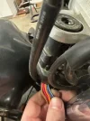
The orange wire connects to the red wire behind the wire cover before the wires get to the connector:
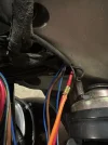
Here are the connectors:
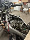
The red wire (and orange wire) is constant +12V from the battery, and when switched, the brown wire (which becomes brown/blue after the connector) gets 12V. This then goes to the signal, headlight, ignition and tail light fuses. (white connector in picture)
The two remaining wires (red connector) are blue/yellow (which becomes blue/white after the connector) which goes to the ECU, and blue/black which goes to the starting circuit cut-off relay and the clutch switch. When the main switch is off, these two wires get 0V, when on they get 0.7V.
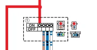
For reference, this is the connector pinout from the wiring diagram:
When switched on, there is continuity between the red and brown wires, and between the blue/white and blue/black wires.
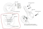
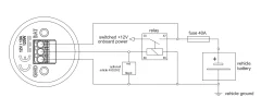
Here are the instructions from motogadget website:
Can anybody help me figure out if it is possible to use this device and if so, how the heck to wire it? The blue/white and blue/black wires are really throwing me off.
Thank you in advance for your help and guidance.
I am trying to wire in a motogadget mo.lock nfc ignition using their optional wiring harness. I have linked the products for reference. Note: I am not using the mo.unit.
My existing ignition looks like this:
The orange wire connects to the red wire behind the wire cover before the wires get to the connector:
Here are the connectors:
The red wire (and orange wire) is constant +12V from the battery, and when switched, the brown wire (which becomes brown/blue after the connector) gets 12V. This then goes to the signal, headlight, ignition and tail light fuses. (white connector in picture)
The two remaining wires (red connector) are blue/yellow (which becomes blue/white after the connector) which goes to the ECU, and blue/black which goes to the starting circuit cut-off relay and the clutch switch. When the main switch is off, these two wires get 0V, when on they get 0.7V.
For reference, this is the connector pinout from the wiring diagram:
When switched on, there is continuity between the red and brown wires, and between the blue/white and blue/black wires.
Here are the instructions from motogadget website:
- Cable from relay via fuse to +12V and ground: 60 cm /23.62"
Cable from relay to mo.lock NFC: 150 cm /4.92'
Cable from relay to on-board power supply: 150 cm /4.92' - Integrated relay socket
- Integrated 40A vehicle main fuse
- Pre-assembled battery connection (M6 ring eyelets)
Can anybody help me figure out if it is possible to use this device and if so, how the heck to wire it? The blue/white and blue/black wires are really throwing me off.
Thank you in advance for your help and guidance.