
• Welcome to the Yamaha FZ6 Forums. Member registration disables ads and allows you to post and share. Register Here.

Need Help Yamaha FZ6N – D09 showing 18.6V + persistent fault code 46

Rob3rto

New Member
Joined
Sep 26, 2026
Messages
6
Reaction score
0
Points
1
Location
Romania
Visit site
Hi everyone,
I have a Yamaha FZ6N, 2005, and I am currently trying to diagnose a strange running problem together with a persistent fault code 46.
The bike starts and runs normally when cold, but as it gets warm the idle becomes unstable, drops progressively (sometimes to around 600–700 rpm) and the engine can stall. After cooling down, it starts and runs again.
The thing that really caught my attention is the diagnostic code D09.
According to the service manual, D09 is fuel system voltage / battery voltage, and it should normally show approximately the actual battery voltage (~12 V with the engine stop switch ON).
However, on my bike:
Engine stop switch OFF → D09 = 0
Engine stop switch ON → D09 immediately goes to 18.6 V
It stays fixed at 18.6 V
Actual battery voltage at the same time is around 12.0–12.5 V
Fuel pump voltage is around 11.8 V
ECU red/white power supply is around 12.15–12.5 V
Injector supply voltage is approximately the same as the battery voltage
Coil supply voltage is also approximately the same as battery voltage
So I definitely do NOT have 18.6 V physically measured anywhere on the bike.
I have also checked the charging system:
Battery at rest: ~12.5 V
Engine idling: ~13.0 V
At 5000 rpm: ~14.0 V
Charging voltage remains approximately the same even when the engine is hot.
I also tested the ignition coils through diagnostic mode:
D30 – coils #1/#4: 5 sparks generated
D31 – coils #2/#3: 5 sparks generated
Both sides behave approximately the same.
During the test, battery voltage was around 12.25 V
Coil supply was around 12.16 V
I have also checked the injector voltage:
Around 1000 rpm: 12.4 V
When the engine drops to 600–700 rpm: around 11.7–11.8 V
Battery voltage measured at the same time is essentially the same, so there doesn't seem to be a significant voltage drop to the injectors.
The strange part is also the fault code 46.
Code 46 appears immediately when I turn the ignition ON. It does NOT appear only after starting the engine or after the engine gets hot. It is already there on the meter/cluster as soon as the ignition is switched on.
I have checked the wiring and connectors related to the FI system many times, including the ECU connector, FI relay/starting circuit cut-off relay, fuel pump and injector wiring. I also inspected the pins and connectors for loose or pushed-back terminals.
The FI relay is marked:
5VK-81950-30
G8R-30Y-V3
I have also checked the power supply circuits and measured the relevant voltages directly rather than relying only on the diagnostic display.
Another thing that makes me suspicious of the ECU is that the ECU housing/sealing around the main connector looks damaged/cracked, and there is visible evidence around the connector area that makes me wonder whether moisture/corrosion or an internal ECU problem could be involved.
At this point, the thing I cannot explain is:
Why does D09 show exactly 18.6 V when the actual battery voltage is only ~12 V, and why does it remain fixed at 18.6 V?
Could a faulty ECU, ECU ground, internal voltage sensing circuit, or another wiring issue cause D09 to display 18.6 V even though the actual supply voltage is normal?
I am planning to check the ECU grounds next using a voltage-drop test, rather than just checking continuity.
For reference, the service manual states that:
D09 = fuel system voltage (battery voltage), normally approximately 12.0 V
Fault code 46 = FI system power supply is not normal
So I would really appreciate any input from someone who has seen D09 stuck at 18.6 V on an FZ6.
Has anyone experienced this before? Could 18.6 V on D09 be an ECU/ECU ground/internal ECU issue, or is there something specific in the FZ6 wiring that I should check?
Thanks!
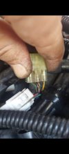
 
Ah my friend, I am having similar trouble as you are. I had the opposite symptom, low d09 and crank but no start intermittent situation.
I be been checking various electrics exactly as you did. I understand you already know most of the following, but here it is:
- don't rely on continuity tests, measure voltage drops while on load ( engine working at idle is enough for most cases). It is enormously more revealing.
- check voltage drop between the black ecu ground and chassis. Also ecu ground and battery negative terminal. You can use a  needle probe in the black cable close to the ecu so you can do your measurement.
- check voltage drop between battery negative and chassis.
- cold ok, hot not ok my mind goes to the cps sensor. You can measure its resistance for a start, cold and hot. It is a component that likes to fail when hot and restores operation when cold. You can also check its waveform using a handheld oscilloscope. You ll get much more revealing info.
- clean the ecu connector and pins if you haven't already. Also clean every connector you see, especially the one in the picture which goes to most of the sensors ( connector D in the service manual diagram)
- clean the ground spiders. Small rectangular connectors taped in the main harness two of them ( I am not sure if there are more) are under the tank area, one is closer to the ecu. The white connectors to the right side of this pic
- check the ground wire underneath the instruments cluster too.
 

Attachments

  • Screenshot_20260926_233824_Gallery.jpg
    Screenshot_20260926_233824_Gallery.jpg
    192.7 KB · Views: 1
Last edited:
I can’t think of a single reason (or source) to have more than battery voltage on a line - especially with out a running engine. Even a capacitor that is able to feed past a failed diode would only deliver a short burst current…not a sustained 18vdc.

I’m not aware of any op-amps in the ECU.

Congratulations, you have a unique problem.
 
Ah my friend, I am having similar trouble as you are. I had the opposite symptom, low d09 and crank but no start intermittent situation.
I be been checking various electrics exactly as you did. I understand you already know most of the following, but here it is:
- don't rely on continuity tests, measure voltage drops while on load ( engine working at idle is enough for most cases). It is enormously more revealing.
- check voltage drop between the black ecu ground and chassis. Also ecu ground and battery negative terminal. You can use a  needle probe in the black cable close to the ecu so you can do your measurement.
- check voltage drop between battery negative and chassis.
- cold ok, hot not ok my mind goes to the cps sensor. You can measure its resistance for a start, cold and hot. It is a component that likes to fail when hot and restores operation when cold. You can also check its waveform using a handheld oscilloscope. You ll get much more revealing info.
- clean the ecu connector and pins if you haven't already. Also clean every connector you see, especially the one in the picture which goes to most of the sensors ( connector D in the service manual diagram)
- clean the ground spiders. Small rectangular connectors taped in the main harness two of them ( I am not sure if there are more) are under the tank area, one is closer to the ecu. The white connectors to the right side of this pic
- check the ground wire underneath the instruments cluster too.
Thanks for your detailed reply, my friend. I have now done most of the checks you mentioned, and I have some additional information that might help.
I checked the ECU grounds, both the black (B) and black/white (B/W) wires, using voltage-drop measurements. The voltage drop is essentially 0.0 V / only a few hundredths of a volt, so the ECU grounds appear to be good.
I also checked the ECU power supply. The battery voltage is approximately 12.5 V, and I have approximately 12.5 V at the ECU power supply as well. I also measured between the ECU R/W power supply and ECU ground, and I get approximately 12.5 V.
I disconnected, inspected and cleaned the ECU connector and pins, as well as several other connectors and terminals in the system, and reconnected everything properly.
The charging system also seems to be working normally: approximately 13.0 V at idle and 14.0 V at 5000 rpm, and I don't see a significant change when the engine is hot.

The really strange part is D09.
This morning, after the bike had been sitting overnight at around 4°C with high humidity, I started it completely cold. Fault code 46 and the check-engine light initially appeared, but a few seconds after starting the engine, both disappeared from the dashboard by themselves and did not come back. The motorcycle then ran perfectly.
I let it run for approximately 40–50 minutes, stopping and restarting it several times, and it continued to run perfectly.
During that period I checked D09 and it showed the correct voltage, around 12.5 V, matching the actual battery voltage.
About three hours later, the outside temperature had increased to around 16°C. I started the bike again and initially it ran well. After stopping and restarting it, the problem returned. The engine started running badly, fault code 46 appeared again, and D09 went back to approximately 18.6 V.
When D09 shows 18.6 V, the actual battery voltage is still approximately 12.5 V, and the ECU power supply is also approximately 12.5 V. I also have approximately 12.5 V between R/W ECU power and ECU ground.
D09 sometimes fluctuates slightly, for example 18.6 → 18.5 → 17.9 V, but it remains in that range.
So at the moment I have:
Battery: ~12.5 V
ECU power supply: ~12.5 V
R/W ECU → ECU ground: ~12.5 V
ECU ground voltage drop: ~0.0 V
D09: ~18.6 V
This is what I find very strange.
The ECU housing/sealing around the main connector is also cracked. I sealed that area, so I am wondering if moisture or previous electrical stress could have affected something inside the ECU.
Since you had the opposite problem with low D09, do you have any idea how the ECU actually measures the voltage for D09? Is there a separate voltage-sensing wire going into the ECU, or is the voltage measurement done internally from the ECU power supply?
I am trying to determine whether I should continue looking for an external wiring/connector problem or start suspecting an internal ECU voltage-sensing problem.

Thank you, i really apreciate.
 
So 1st time in the morning error appears d09 was fine engine worked fine. Later on next attempt error reappeared but d09 was 18v and engine malfunctioned, correct?

I would connect a voltmeter permanently on the efi line instead of the battery to see the voltage the exact time the engine malfunctions.

I have removed the efi fuse (fuse 5 on diagram) and measured 0V at d09 (kill switch on) and ~12V with the fuse re-inserted, so the ecu definitely monitors the voltage on the red-blue wire. The ecu power supply is the red/white as far as I can understand from the circuit diagram.

Edit:
Did you measure the ecu ground when d09 was 18v or 12v ?
I would connect a voltmeter on red-blue and black wires close to the ecu to see what the ecu actually sees during the problem, not during normal operation. Intermittent problems are the most frustrating, i can understand you situation trust me. The insulation hole from your pin probe can be sealed with liquid electric "tape" later on.
 
Last edited:
So 1st time in the morning error appears d09 was fine engine worked fine. Later on next attempt error reappeared but d09 was 18v and engine malfunctioned, correct?

I would connect a voltmeter permanently on the efi line instead of the battery to see the voltage the exact time the engine malfunctions.

I have removed the efi fuse (fuse 5 on diagram) and measured 0V at d09 (kill switch on) and ~12V with the fuse re-inserted, so the ecu definitely monitors the voltage on the red-blue wire. The ecu power supply is the red/white as far as I can understand from the circuit diagram.
Yes, that's correct regarding the first start in the morning and the second attempt a few hours later.

I can also try connecting the voltmeter directly to the EFI supply and monitor the voltage when the error appears.

However, the strange part is that the error appears even with the engine OFF. In that situation, I don't see how the ECU could actually have 18.6 V on the EFI line, since the engine is not running and the charging system is not generating any voltage.

If the engine were running, I could understand a possible overvoltage situation, but with the engine OFF it doesn't make much sense.

Nevertheless, I will measure the voltage directly on the EFI supply and see what happens exactly when the error appears.
 
I edited my answer as you were replying, sorry.

Yes you are right about the absence of real high voltage generation but then again we don't know how the ecu actually senses/ calculates it, perhaps with a comparator towards a reference zener or something.
 
I edited my answer as you were replying, sorry.

Yes you are right about the absence of real high voltage generation but then again we don't know how the ecu actually senses/ calculates it, perhaps with a comparator towards a reference zener or something.
Yes, I measured the ECU ground when D09 was showing 18.6 V. I also measured the voltage directly between the red-blue and black wires at the ECU connector.
I have some back-probing tools that allow me to access the ECU connector alongside the wires without damaging the insulation, so I can take measurements directly at the connector.
I'm also an electrician by profession, so I have the necessary tools and experience to carry out these electrical checks.

Yes, that makes sense. We don't know exactly how the ECU measures or calculates D09 internally, so the 18.6 V reading could potentially be the result of an internal sensing/reference circuit rather than an actual 18.6 V on the EFI line.

There is also one more thing I discovered. Two months ago i found a problem with the voltage regulator connector. The connector was getting extremely hot — when I touched it, it was too hot to keep my hand on it.

I suspect that something may have happened at that point, possibly a voltage spike or an unstable charging condition, which could have affected the ECU. I cannot say for certain that this is what caused the problem, but it is definitely suspicious.

In any case, I have already ordered another ECU as a replacement, because at this point I don't see many other checks that could give us a definitive answer.
 
https://share.gemini.google/yBNpnIBWckue

AI assumptions are often wrong, especially when the prompt is not detailed, but do check the kill switch too, you don't have anything to loose. Voltage drop between red/white and red/black on the cutoff relay is a quick way.

Measure also the igntion switch contacts+ connector ( voltage drop between permanent and switched supply on the fuse box)

Measure when the problem occurs.
 
To me, it was obvious from the first post 😀

You ordered a used or new ecu ? Cost? What about the immobilizer?
I have already ordered a complete ECU/immobilizer set here in Romania for €250.

The set includes the ECU, ignition switch/key set, immobilizer, fuel tank cap and seat lock. The seller will test everything before removing it from the motorcycle — he will start the engine and show me that everything is working properly. Only after confirming that it works will he remove the parts and send them to me.

Once I replace the ECU and test the motorcycle, I will come back to this thread and update you with the results. I will confirm whether the ECU was actually the cause of the problem, so that this information can also help other people who may encounter the same issue in the future.
 
Back
Top