Heated grips, voltmeter, 12v outlet on same circuit?

MattR302

Awesomeness, Inc.
Joined
Apr 19, 2012
Messages
621
Reaction score
38
Points
28
Location
New Haven, CT
Visit site
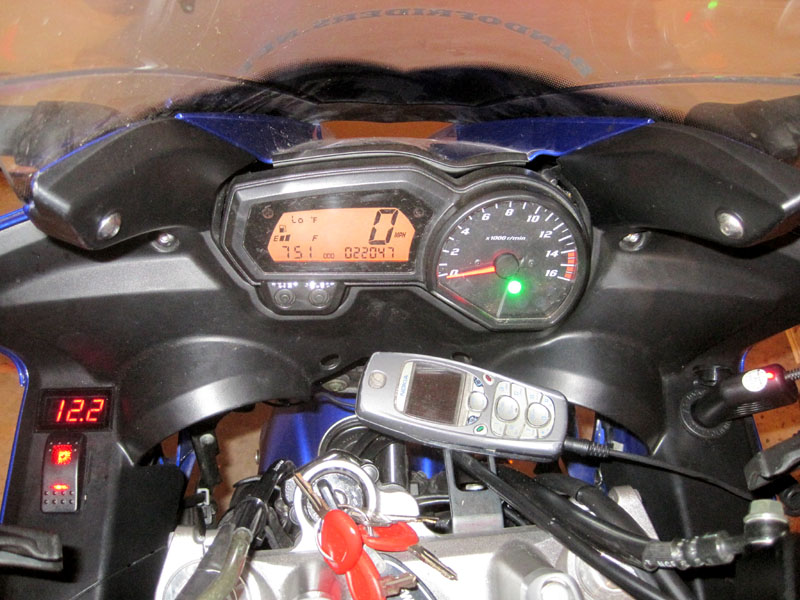
So this weekend I'm planning on finally installing my grip heaters which have been sitting in my basement for like 4 years. They are rated at 3A/36W. I will be running them on a circuit from the battery switched by a relay. I will also be installing a small digital LED voltmeter, and a 12v cigarette lighter outlet. The outlet will only be used for charging my GPS, phone, or Sena, so it shouldn't be pulling much current. Anyone see any problems running these all on the same circuit?
 

Motogiro

Vrrroooooom!
Staff member
Moderator
Elite Member
Site Supporter
Joined
May 8, 2008
Messages
14,993
Reaction score
1,159
Points
113
Location
San Diego, Ca.
Visit site
Sounds fine to me. Just make sure there is an inline fuse installed at the battery where it feeds your relay.:)
 

TownsendsFJR1300

2007 FZ6
Site Supporter
Joined
Feb 7, 2009
Messages
12,531
Reaction score
1,176
Points
113
Location
Cape Coral, Florida, USA
Visit site
Last edited:

MattR302

Awesomeness, Inc.
Joined
Apr 19, 2012
Messages
621
Reaction score
38
Points
28
Location
New Haven, CT
Visit site
I'm using one of the cheap $5 ones from ebay, just search "digital LED waterproof voltmeter". I brought it to work and checked it against a very expensive power supply, and it was within .1 volts.

If you tapped into a running light, that would be after the voltage regulator, so you wouldn't be directly reading battery voltage.
 

Motogiro

Vrrroooooom!
Staff member
Moderator
Elite Member
Site Supporter
Joined
May 8, 2008
Messages
14,993
Reaction score
1,159
Points
113
Location
San Diego, Ca.
Visit site
Running light should be good for the volt meter. If you have any question as to any voltage drop there may be, hook the volt meter to the battery first and then the running light circuit. Should be little difference and plenty close enough to see abnormal behavior. If your lighter socket is mounted at the front of the bike just run the volt meter from that circuit?:)

Sent from Moto's Droid using Tapatalk 2 :mikebike:
 

texcollect

Crotchety Old Fart
Joined
Jul 24, 2009
Messages
659
Reaction score
7
Points
0
Location
Katy, TX
Visit site
I decided that I didn't need to know the exact voltage, just the range so I bought one of these.

From 12.5V to 13.2 V it shows Amber and from 13.2V up it shows Green. Below 12.45V it shows various combinations of flashing Red to explain exactly how screwed you are !!

It is wired directly to the output of my switched circuit before it feeds my aux lights and my GPS etc.
 

TownsendsFJR1300

2007 FZ6
Site Supporter
Joined
Feb 7, 2009
Messages
12,531
Reaction score
1,176
Points
113
Location
Cape Coral, Florida, USA
Visit site
Running light should be good for the volt meter. If you have any question as to any voltage drop there may be, hook the volt meter to the battery first and then the running light circuit. Should be little difference and plenty close enough to see abnormal behavior. If your lighter socket is mounted at the front of the bike just run the volt meter from that circuit?:)

Sent from Moto's Droid using Tapatalk 2 :mikebike:

The rt ft running light is where I have my GPS tied into. I'd likely just wrap another line into the "Posi Tap" already there...

Thanks guys..
 

regder

Junior Member
Joined
May 3, 2008
Messages
515
Reaction score
5
Points
18
Location
Toronnto
Visit site
Might not be a bad idea to setup an accessory fusebox so you can run everything on their own circuit and it makes connecting more things easier in the future.
 

TownsendsFJR1300

2007 FZ6
Site Supporter
Joined
Feb 7, 2009
Messages
12,531
Reaction score
1,176
Points
113
Location
Cape Coral, Florida, USA
Visit site
For OP, once you're past a couple electrical doodads it just makes life so much easier, especially with our battery being under the tank.

Added a heated Gerbing's wire lead in a minute the other day.

Oh, ok, wasn't sure...

+1 on on a Powerblock of some sort.

Mines on the inner right side fairing with ALL the farkles running thru it and fused after it:
 
Last edited:

MattR302

Awesomeness, Inc.
Joined
Apr 19, 2012
Messages
621
Reaction score
38
Points
28
Location
New Haven, CT
Visit site
Yeah, I was thinking about some kind of powerlet/fuseblock, but I think I should be all set without it. The voltmeter and 12v outlet won't be drawing much juice, so I'm not worried about putting them on the same circuit as the grips. I can't picture myself adding anything else really. And if I ever did need something more from the 12v outlet, like an air compressor, I'd be turning the grips off when I used it.

For my heated gear, the input power on my heat controller is connected to a 12v SAE connector, so I just plug it into my battery tender lead.
 

MattR302

Awesomeness, Inc.
Joined
Apr 19, 2012
Messages
621
Reaction score
38
Points
28
Location
New Haven, CT
Visit site
Got this little project all wrapped up and took a bunch of pictures. I'm pretty happy with the way it turned out. I spent quite a bit of time planning out my wiring and the schematics.

10611804416_4bd17a0990_o.jpg

After powdercoating the handlebar, first step was putting on the grips. Clutch side got about 4 wraps of Kapton tape first (hindsight I would've put a couple more, since the throttle side is a little warmer on high). I put zip-ties around the wires where they leave the heater as a strain relief. (After this pic, I switched it to a black ziptie, as it hides a little better and the head was a little smaller than this one.)


10612032733_b6022a7ae0_o.jpg

Shaved off a bit of each grip to allow for the ziptie

10612033503_4730ec62a5_o.jpg

Relay Wiring. I bought a fused battery tender lead for $5 and cut off the SAE connector. On the relay connector, the red lead is the NC outlet (not used) cut and insulated. White is the switching source. Blue is connected to the positive lead. The ground side of the battery terminal lead splices into the black relay connector lead. Yellow is the switched power out.

10611802234_590fb04be1_o.jpg

White lead soldered to the crimped connector on the starter relay.

10611777465_0b53561124_o.jpg

2 sets of ring terminals on the battery now, new plus my existing battery tender lead.

10611807616_7982542a66_o.jpg

Relay velcroed to the top of the battery box, everything tucked in nicely.

10611803384_4f2cf1b2e5_o.jpg

Now, how should I run the wires to the grips neatly? Leaving a little extra on the throttle side to allow for WOT with no interference, I followed the wire loom down...

10611803634_cd979eafa4_o.jpg

...and into the frame, in front of the battery...

10611778675_dd602f98ef_o.jpg

...and out the left side, where it met up with the clutch side wires, and the yellow (switched power) and black (ground) wires from the relay.

10611774135_034e26a492_o.jpg

I used a trailer wiring connector to connect all the bike-side wires to my inner-fairing wires. The grounds (red from the grips, black from the relay) get tied to the white wire (exposed pin), the yellow power wire connected to the brown, and the whites and blues (high/low from the grips) connected to the green and yellow.

10611799384_19d6209584_o.jpg

Back side of the inner fairing. Voltmeter and SPDT switch mounted on the left side, 12v outlet mounted on the right. The brown power wire splits to the outlet, the voltmeter, and the center pin on the switch. Ground wire splits to outlet, voltmeter, and the ground pin on the switch (LED switch). Green and yellow to the high and low sides of the switch. So with this setup, I can just unplug the trailer connector and remove the inner fairing.

10611799324_564a98c355_o.jpg

Everything back assembled, looks pretty clean.

10611799024_d92ec7f4be_o.jpg

Everything powered up, voltmeter working, phone charging, grips heating!

Here's the only snafu I ran into that drove me nuts for about an hour. I used this type of switch for the grips. It's got a big light for high, and a smaller light for low. Cool, in theory. But, with the way the Symtecs heaters are wired, it's not two separate circuits for high and low. The low circuit uses the high circuit, plus an additional length to increase the resistance. This results in the low side of the switch seeing 12v when the switch is on high, and the high side of the switch seeing ~6.5v when switched on low. Hence both LED's illuminating on both high and low.

To fix this, I would either need to open up the switch and install a couple small diodes between the switched poles and the LED's... or put diodes capable of handling the full 3+ amps on the green/yellow wires coming from the switch. But a 4amp diode would drop the voltage going to the grips by about 0.8 volts, making them slightly cooler, so I'm not sure I want to do that just yet.
 

HaChayalBoded

Junior Member
Joined
Jan 13, 2010
Messages
115
Reaction score
0
Points
16
Location
NYC
Visit site
Voltmeter should always be connected to either the battery or the alternator (in the case of the FZ-6 the output of the rectifier\regulator) instead of a "hot" connection like the headlight.

The reason for this is that after all the wiring, connectors, wiring, more connectors you end up losing nearly a volt of power. Now every bike is different.

But go ahead and check for yourself. Take a reading from the battery, and then take a reading from the + terminal of your headlight sockets. I betcha it's lower.

This is the reason many use a headlight wiring upgrade kit. Regaining that volt actually nearly doubles your lighting output.

Luminosity is not linear. IE a 10% increase in voltage will not give you a 10% increase in lumens, but closer to an 80% increase.

Anyway, that was more info that you asked for, but it's something to think about.
 
Top